Top 8 reasons that rocketry is just like Pokemon

I grew up playing the original Pokemon games on Game Boy Color (Pokemon Red, specifically). The animated show was also popular at that time, and I’d watch an episode or two every morning before heading off to school. At the end of every episode was the “Poke Rap,” and I’d sing/ rap along since I knew it by heart. I’ve played many more Pokemon games since the days of Red/Blue (and Yellow), and I’ve seen additional seasons of the show. The characters change, and they keep adding more Pokemon. But I’ll always retain a certain fondness for the original 150.

Years later, I’ve discovered high power rocketry, and I was recently struck by the similarities. Below I’ve compiled a list of why rocketry is similar to Pokemon:

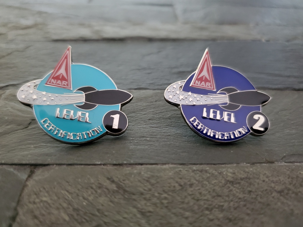
8. Collecting badges.

I recently earned my level 1 and level 2 certifications in high power rocketry (HPR) from the National Association of Rocketry (NAR), and NAR sent me these two badges. Now I can put these badges on the inside of my jacket and proudly display them whenever someone challenges my rocketry credentials – and after you defeat six more gym leaders to collect additional badges, you too can compete in the rocketry league!

close up of metal badges that say level 1 and level 2 certification
classy!

7. Expert guidance from Professor Oak.

You’ll find some great mentors – more experienced rocketeers – who can provide advice and wisdom on rocketry. They may or may not be actual professors named after plants (Oak, Ivy, etc.).

6. Friends like Misty and Brock.

You’ll meet lots of people on your journey and make some great friends along the way, even if you have to steal their bicycle or defeat them in battle first.

5. Team Rocket.

Enough said.

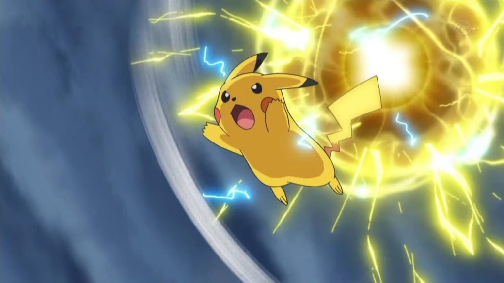
4. A frequently “shocking” experience.

With electrical ignition systems that are used to ignite all modern rocket motors, there’s no shortage of electricity themed puns – just like with every Pikachu attack!

pikachu jumping and using electric attack
a real shocker!

3. A superior rival.

Like Ash and Gary, you’ll discover and battle opponents, and there will always seem to be one who is one step ahead of you, at every turn. Unfortunately, you’ll probably never quite catch up.

2. Mom.

No matter how much you’ve been through and how much you’ve grown, there is always the risk that your mom may show up at the launch site, yelling at you to remember to change your underwear, and otherwise generally embarrassing you in front of a large crowd.

1. Bitter failures and setbacks.

There will be plenty of failures, devastation, and general catastrophe in your future, whether you’re battling with Pokemon or launching rockets. But you’ll learn some important life lessons along the way. And, in any event, things will be neatly wrapped up by the time the credits roll!

High Power Rocketry: L2 Certification Flight

Officially level 2 certified!

rocket launching into the blue sky, with fire and smoke below
textbook flight

Fulfilling a 2020 goal

I really started getting into rocketry last fall, less than a year ago, and I had set some goals for 2020 when the year began. My goals included getting level 1 and level 2 certifications in high power rocketry (HPR) through the National Association of Rocketry (NAR).

I think 2020 threw some curveballs at just about everybody, myself included – but after a few false starts and delays, I was able to launch my first high power rocket in central Washington on a beautiful day in June, and as I wrote about previously, I got my L1 cert.

I deliberately chose and constructed a rocket that could be used for both L1 and L2 certification (i.e. it is capable of launching on a more powerful motor), and I built it to be dual deploy capable. I also had plenty of time to study for the written exam, which is required after the L1 certification but prior to the L2 flight. Timing is everything.

Because of this, I was able to do everything in a single day – L1 flight, L2 written exam (which I passed, of course), and L2 flight. I had more than six months to prepare for this day, so it’s not particularly impressive!

white rocket with orange and yellow parachutes lying on ground in green field
a safe landing

L1 vs. L2 flights

On the L1 flight – the maiden voyage – I didn’t want to take any unnecessary risks and decided to keep it as simple as possible, so I didn’t attempt using any electronics or dual deploy. The rocket separated through a simple motor ejection charge.

But for the L2 flight, I wanted to try the flight computer and dual deploy. I was a little nervous because while I checked and rechecked everything in advance, this was still the first actual attempt and there were a lot of firsts: first time using any flight computer or black powder charges, first time arming the electronics on the launch pad, first time using the ground station to communicate via radio with the rocket (using a laptop with the appropriate software and a connected Yagi antenna), etc.

Everything went smoothly, from the launch (see first photo above) to deployment of the drogue parachute at apogee and the main parachute closer to the ground. I recovered the rocket without any damage.

white rocket with text "improbable ventures" lying on ground in green field
mildly improbable

L2 flight data breakdown

What’s particularly cool is the flight computer not only fires multiple pyro charges (and therefore controls the rocket’s separation and deployment of two parachutes), but it also contains an altimeter and other sensors that record the rocket’s maximum height and its descent speed.

For my L2 flight, the rocket reached 3,506 ft, with a maximum speed of 599 ft/sec (Mach 0.5). In other words, the rocket’s max speed was about one-half the speed of sound.

The descent rate under the drogue parachute was 39 ft/sec, and under the main parachute it was 27 ft/sec. The HyperLOC 835 is a fairly lightweight cardboard rocket with a gross liftoff weight (that is, a weight including the motor, parachutes, and everything else inside) of only about 6 lbs, and this descent rate was more than sufficient for a safe landing.

All in all, this was a fantastic experience. A four hour drive each way made this a very long day, but it was absolutely worth making the trip. Inevitably, I also learned a tremendous amount – for example, how to set up a large rocket on the pad and launch rail, how to use the flight computer and ground station software, etc. I also learned what types of things that I could do better next time. Overall, I’m even more excited about future launches – trying out new techniques, flying on even more powerful motors, and capturing data with the flight computer to beat my own previous records!

How to build a fiberglass rocket, part 5: nose cone

Like many fiberglass rocket kits, the Darkstar Extreme has an aluminum-tipped nose cone. The aluminum tip is for more than just show: it has a couple of structural purposes.

One is the manufacturing method of the nose cone itself. The process uses “filament wound fiberglass,” which involves placing resin-impregnated fibers around a mandrel (a gently tapered cylinder). It is difficult to make this come to a point, and instead the manufacturer just shortens the nose cone and puts an aluminum tip on.

Another purpose is that during flight, the tip of the nose cone absorbs the most heat, and aluminum is a better material to use for this specific part of the rocket.

grey nosecone
aim with the pointy end

So, the question for me now is: how to connect the nose cone to the rest of the airframe?

You might be asking: how hard can that be? And you’d be right; it isn’t particularly difficult. But some nose cones have a portion that can fit inside the rocket body, as though there’s a built-in coupler. This nose cone, though, is the same diameter as the rocket body and will not fit inside it.

The good news is, the rocket comes with a 6 inch long coupler. Half goes inside the nose cone, half inside the airframe (payload section). On the nose cone side, I just epoxied them together to create a permanent bond. On the other side, I drilled three small holes through the airframe (and coupler) and inserted nylon screws (shear pins). This allows everything to stay together until a large force is applied mid-flight and the airframe separates from the nose cone, deploying a parachute.

The bad news, however, is that I need to attach a kevlar cord to the nose cone somehow, and the best way to do this is to put a bulk plate with a forged eye bolt on one side of the coupler. Either side will do, but it makes sense to put it on the side that goes a few inches into the nose cone, rather than the side that comes a few inches out, since that increases the available storage space inside the rocket for things like the parachute and 25 feet of kevlar cord.

The kit came with a fiberglass bulk plate with no edge or lip (see above picture). It will fit inside the coupler, but I don’t feel too confident that epoxy alone will hold it in place. Instead, I ordered another aluminum bulk plate with an edge or lip – the inner part fits inside the coupler, but there is an outer lip that sits above the coupler so it cannot be pulled through, no matter how hard the cord is yanked.

green aluminum bulk plate attached to red fiberglass coupler
a christmas coupler

I epoxied the aluminum bulk plate to the coupler, and then used more epoxy to attach the forged eye bolt (with a long screw attached) and two nuts to the bulk plate itself. There’s no way this setup is coming loose during flight regardless of the forced applied.

view inside coupler, from above
masking tape dam keeping epoxy near walls

Above is a view of the inside of the coupler. I added some masking tape in an attempt to create a very crude barrier or dam, keeping the additional epoxy a bit closer to the edges to seal them.

red fiberglass coupler secured inside grey nosecone
a perfect fit

That’s it! The coupler and nose cone are in good shape, and I’m ready to move on to the next section: my old friend, the e-bay.

How to build a fiberglass rocket, part 4: motor mount

With the airframe of the rocket nearly complete, I just needed to prep the area where fins will eventually go. The rocket is pre-slotted (i.e., it comes with slots already punched out to insert the edge of the fins), but the slots are all too narrow and needed to be sanded quite a bit to widen them.

In addition, I drilled 12 individual holes (one for each side of all 6 fins). Later in this assembly, I’m going to insert the fins into these slots, where their edges will be up against the motor mount tube inside this airframe. I’ll then inject epoxy with a syringe into each hole, and tilt the rocket back and forth to spread it around, ensuring that the fins are strongly secured in place both internally and externally. But I’m getting ahead of myself.

booster section of rocket airframe, with slots for fins
pre-slotted airframe

On to the motor mount tube!

This 75mm fiberglass tube has a slightly smaller diameter than the 4″ rocket airframe. (To be clear, I have no idea why the motor mount tubes are almost universally measured in metric units – 54mm, 75mm, and 98 mm being fairly common in high power rocketry – while the airframe itself is measured in inches. It’s a mystery for the ages.)

There are 4 beige colored fiberglass centering rings: the inner diameter of each ring fits snugly around the motor mount, and the outer diameter of each ring fits inside the larger airframe. The purpose of these rings, as the name implies, is to center the motor mount inside the airframe.

red motor mount with yellow kevlar recovery harness on workbench
motor mount with kevlar recovery harness

The primary goal here is to secure the yellow kevlar recovery harness to the motor mount. Later, I’ll attach a much longer kevlar cord to this one, and the other end of that cord will attach to one end of the e-bay (with a parachute attached as well).

This basically makes sure that the bottom part of the rocket, including the motor, stays linked to the e-bay in the middle of the rocket – and also makes sure that a parachute can deploy, when these parts separate after apogee. Since there’s nothing obvious to hook or attach this cord to on the motor mount, the solution is to simply epoxy it directly to the motor mount.

I measured the width of the cord (1 inch) and marked it on the top centering ring, and then sanded down a 1 inch width on both sides of the inner part of the ring, to allow just enough space for the cord to fit between the ring and the fiberglass tube. About 6 inches of cord are on each side of the tube.

motor mount with recovery harness tucked inside centering ring
before: tucked inside centering ring

After that, I created some very crude “dams” with masking tape since the epoxy is a bit runny before it cures. I put a generous amount of epoxy underneath the cord to bond it to the tube, and then even more on top of the cord, in order to totally encapsulate it.

Here you can see a “before” and “after” picture. I couldn’t quite get all the masking tape off afterwards because some was sealed and bonded (somehow I did not foresee this). But the cord is totally encapsulated. When the epoxy cures, it becomes incredibly hard and is similar to plastic.

recovery harness sealed in epoxy
after: sealed in epoxy

The recovery harness here is now thoroughly secured to the motor mount.

A few notes on epoxy, as this was my first time ever using it. It’s pretty straightforward, but there’s a slight learning curve. I used West System 105 resin and 205 hardener: these are two separate products that come in separate containers with pumps. You add them together (in a ratio of one pump each) into a mixing cup, and then mix them together (I used a popsicle stick) very thoroughly, for several minutes.

Once mixed, the epoxy begins to harden and cure much faster than I initially realized. It also gets very hot, from the chemical reaction – to the point where it’s literally giving off visible steam, and the heat from touching the outside of the plastic mixing cup will burn your fingers.

It’s also a bit runny when spreading, so it really helps to create a barrier or dam with masking tape to keep the epoxy where you want it, as it cures. The tape can easily be removed later.

I was previously used to working with wood glue for cardboard rocket sections and plywood fins, but fiberglass is a whole new experience. Wherever fiberglass pieces need to be permanently attached (e.g., the fins to the rocket body), this two-part epoxy is used, and it’s amazingly strong.

Next up: the nosecone.

What to see at the Museum of Flight in Seattle

I recently had a chance to visit the Museum of Flight in Seattle for the first time – long overdue, in fact, since we moved out to the area more than 18 months ago. It was an impressive place with some great exhibits. In particular, we spent most of the time in the Charles Simonyi Space Gallery, although there was much more to see.

This also comes on the heels of my recent trip to the Henry Crown Space Center at the Museum of Science and Industry in Chicago.

Soyuz (Russian) descent module

One highlight was an actual module from a Soyuz spacecraft. Soyuz was the human spaceflight program in the Soviet Union (and continues today in Russia), and the Soyuz rocket and spacecraft were integral parts of this program. Interestingly, the Soyuz rocket is the most reliable launch vehicle, as well as the most frequently used launch vehicle, in the world. The first Soyuz manned capsule was used in 1967, and Soyuz flights have taken place more than 1,700 times since then, in both manned and unmanned missions.

Life sized model of the Hubble telescope
The Hubble telescope

The exhibit also had some life-size models of things like the Hubble telescope and even a life-size space shuttle that you can climb aboard. Pictures (such as the Hubble, above) obviously don’t do the size of these things justice, although the relatively small floating astronaut next to the telescope helps provide a sense of scale.

The Hubble telescope is of course extremely well known. It was launched into low earth orbit in 1990 and remains in operation today – 30 years later! – and it’s produced countless amazing images of the cosmos.

One thing that I didn’t know was that the Hubble is expected to last until 2030, or perhaps as late as 2040, and that its successor is the James Webb Space Telescope, scheduled to be launched in 2021 – from an Ariane 5 rocket. What a time to be alive!

Museum display titled Rocket Science 101
Rocket Science 101

The space gallery also had a variety of other exhibits, including some interesting info about how rockets work, differences between solid and liquid fuel rockets, and displays related to the world’s largest rockets and orbits. I’m no expert on any of this, and I really enjoyed this “Rocket Science 101.”

I only included a handful of pictures here, but for more, you can check out my Instagram.

The Museum of Flight really has a lot of other exhibits to see as well; in fact, it’s primarily dedicated to aviation and airplanes (e.g. from the early days of flight and the World War I and II era), with only a smaller space dedicated to spacecraft and rocketry. But it’s absolutely worth a visit, whether you live in Seattle or next time you’re visiting.